This is a very simple level indicator that is incredibly easy to make and does not contain transistors or microcircuits. It was assembled in 10 minutes using hinged mounting and works great.
The device connects directly to the speaker and displays the sound level. Can easily be used as a light and music decoration for any speaker or subwoofer.
Will need
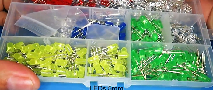
- LEDs -
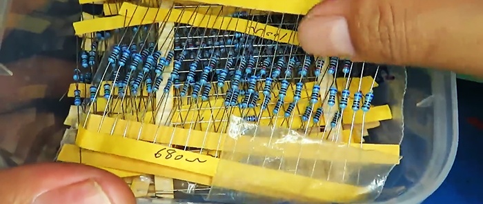
- Resistors 680 Ohm -
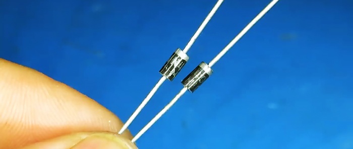
- Diode 1N4007 -
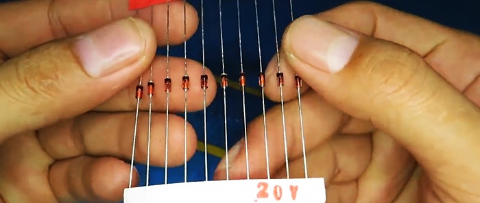
- Zener diode 20 V -
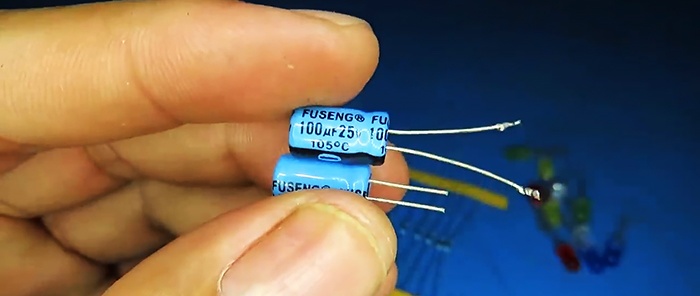
- Capacitors 100 µF 25 V -
Making a level indicator
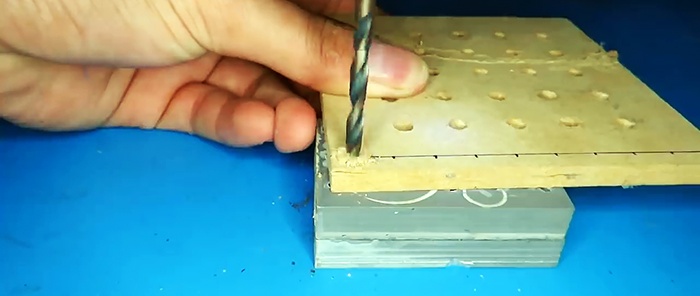
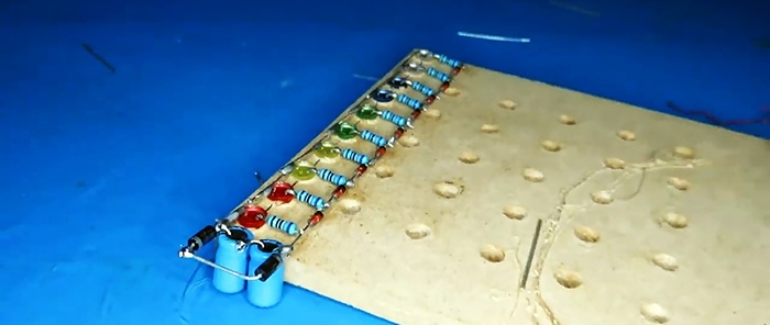
We will make a simple template from a piece of wooden backing. To do this, mark it along the line into uniform segments, drill holes for LEDs.
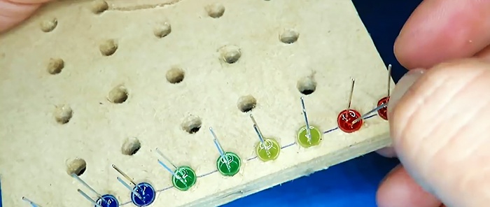
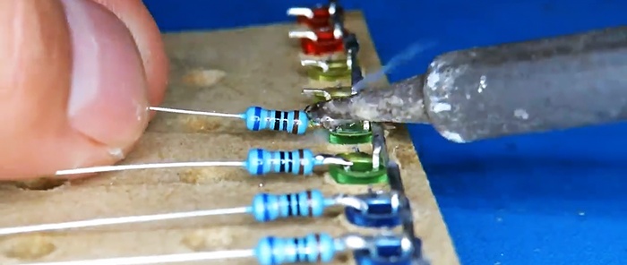
We insert LEDs so that their negative terminal is all on the same side.
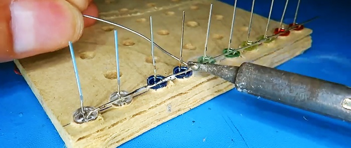
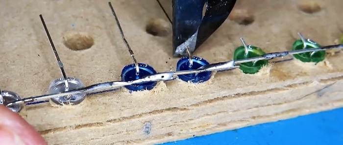
We bend the negative terminal with the adjacent LED and solder all the contacts into a line.
We bend the positive contact and cut it to a minimum.
We take resistors and cut off the contacts on one side. Solder to the LEDs in order.
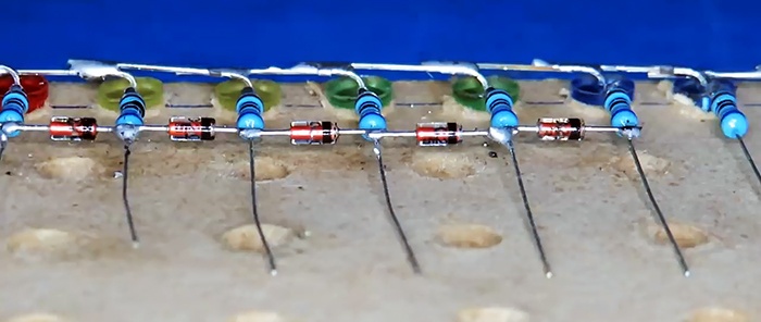
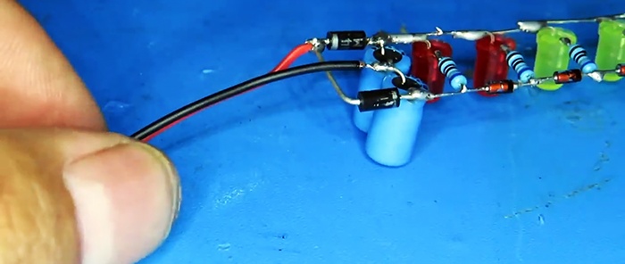
Next, we take the zener diodes, trim their leads and solder them. Pay attention to the position of the cathode and anode.
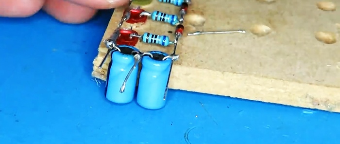
At the beginning we include two capacitors connected in series.
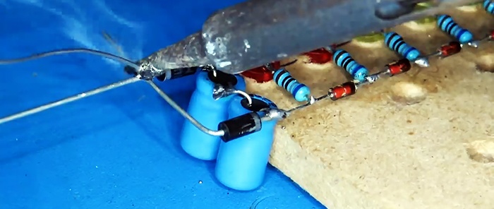
Solder the diodes.
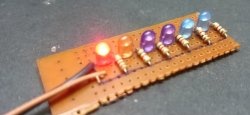
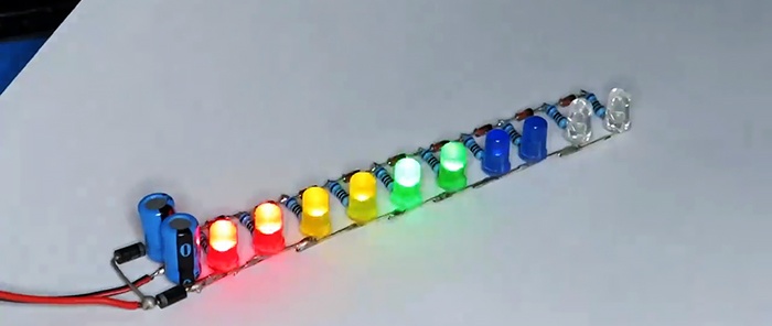
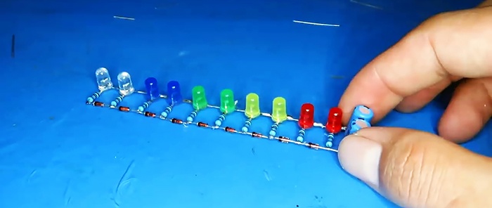
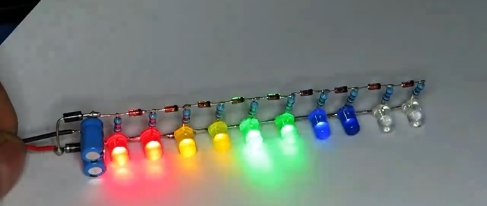
The indicator is ready for use.
We solder the wires to a bunch of diodes, and then to a bunch of capacitors.
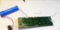
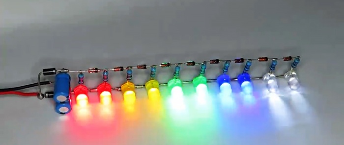
The indicator is connected directly to the dynamic head.
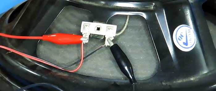
And it works great.
Principle of operation
A voltage doubler is built using diodes and capacitors to rectify and double the input voltage. Next, everything goes to the line with LEDs, a kind of ladder, where the steps are zener diodes, adding to each switching level LED + 0.6 V. Yes, although zener diodes are designed for a stabilization voltage of 20 V, they are turned on in the reverse way and work like diodes with a high reverse voltage. It is quite possible to replace them with 2 ordinary diodes connected in series, but then more of them would be needed.
As a result, during operation, each voltage value at the input “reaches” its LED.
Watch the video
In the video clip you can clearly see the operation of the indicator.