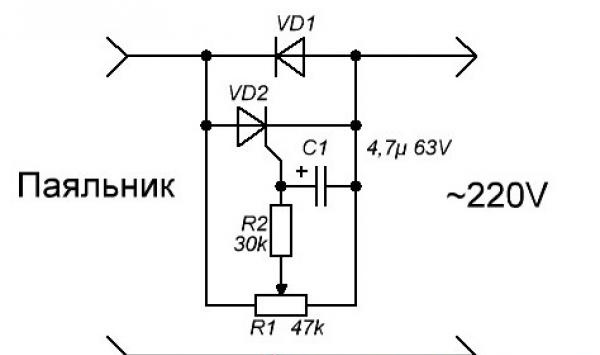
To assemble the device you will need:
- diode 1N4007 or any other, with a permissible current of 1A and a voltage of 400 - 600V.
- thyristor KU101G.
-electrolytic capacitor 4.7 microfarads with an operating voltage of 50 - 100V.
-resistance 27 - 33 kilo-ohms with permissible power 0.25 - 0.5 watts.
-variable resistor 30 or 47 kilo-ohm SP-1, with linear characteristic.
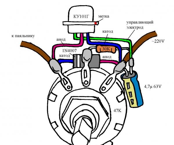
For simplicity and clarity, I drew the placement and interconnection of parts.
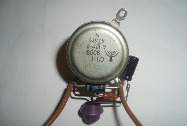
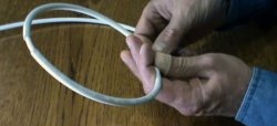
Before assembly, it is necessary to insulate and mold the leads of the parts. We put 20mm long insulating tubes on the thyristor terminals, and 5mm long on the diode and resistor terminals. For clarity, you can use colored PVC insulation removed from suitable wires, or apply heat shrink. Trying not to damage the insulation, we bend the conductors, guided by the drawing and photographs.
All parts are mounted on the terminals of a variable resistor, connected into a circuit with four soldering points. We insert the component conductors into the holes on the terminals of the variable resistor, trim everything and solder it. We shorten the leads of the radio elements. The positive terminal of the capacitor, the control electrode of the thyristor, the resistance terminal, are connected together and fixed by soldering. The thyristor body is the anode; for safety, we insulate it.
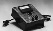
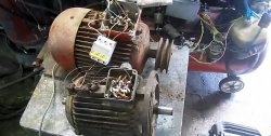
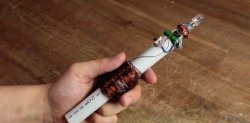
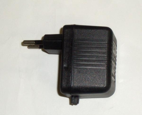
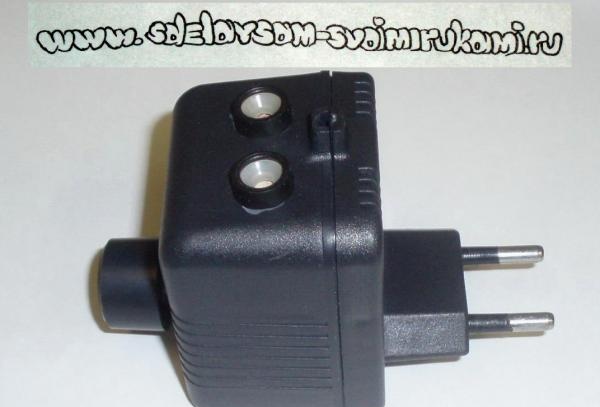
To give the design a finished look, it is convenient to use a housing from a power supply with a power plug.
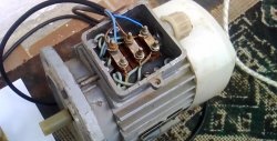
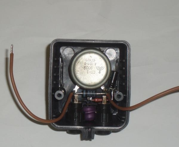
On the top edge of the case we drill a hole with a diameter of 10 mm. We insert the threaded part of the variable resistor into the hole and secure it with a nut.
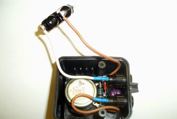
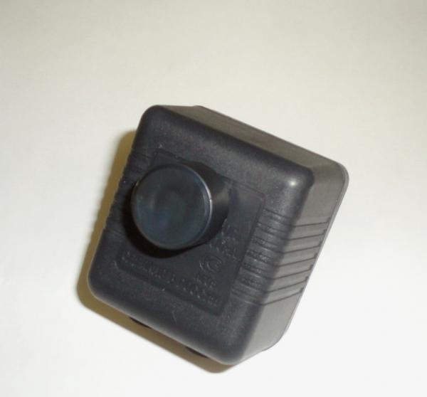
To connect the load, I used two connectors with holes for pins with a diameter of 4 mm. On the body we mark the centers of the holes, with a distance between them of 19 mm. In drilled holes with a diameter of 10 mm. insert the connectors and secure with nuts. We connect the plug on the case, the output connectors and the assembled circuit; the soldering points can be protected with heat shrink. For a variable resistor, it is necessary to select a handle made of insulating material of such shape and size as to cover the axle and nut. We assemble the body and securely fix the regulator handle.
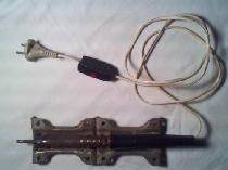
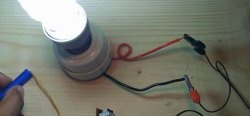
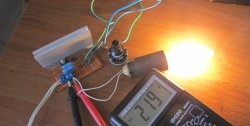
We check the regulator by connecting a 20 - 40 watt incandescent lamp as a load. By rotating the knob, we make sure that the brightness of the lamp changes smoothly, from half brightness to full intensity.
When working with soft solders (for example POS-61), with an EPSN 25 soldering iron, 75% of the power is sufficient (the position of the control knob is approximately in the middle of the stroke). Important: all elements of the circuit have a supply voltage of 220 volts! Electrical safety precautions must be observed.