Usually, everyone is accustomed to the fact that thyristors or triacs are used to regulate power, and autotransformers are used to regulate voltage. But there is also a variant of the regulator, assembled on just one transistor, which has different characteristics. It can easily find its application in amateur radio homemade products.
Details
- Transistor IRF740 - http://alii.pub/6cfb0k
- Diode bridge 400 V 10 A - http://alii.pub/5m5na6
- Zener diode 12 V - http://alii.pub/5myg53
- Resistor 500 kOhm - http://alii.pub/5h6ouv
- Variable resistor 500 kOhm - http://alii.pub/5o27v2
Regulator circuit
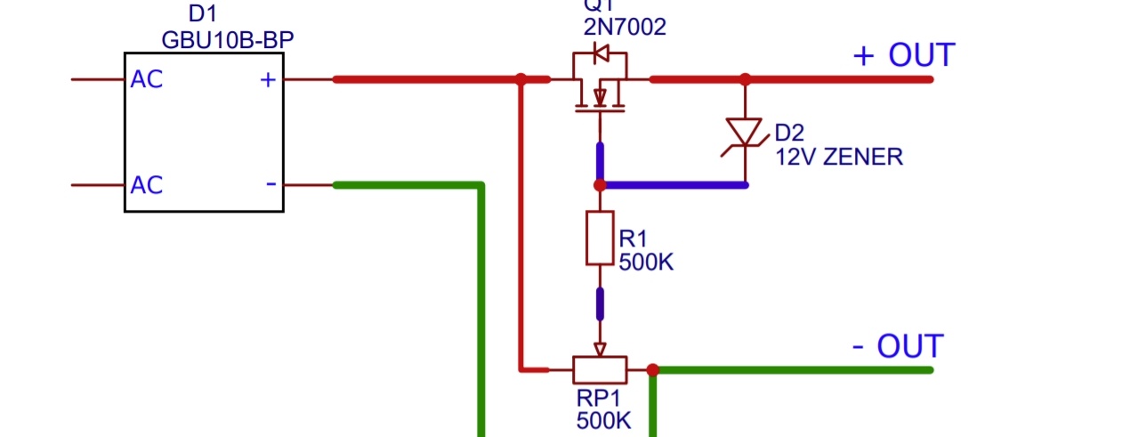
The elementary circuit is based on an IRF740 field-effect transistor. Its operating voltage is up to 400 V, current is up to 10 A. But this does not mean that it can be controlled with a power of 4 kW. After all, the power dissipation of the transistor is only 125 W.

Manufacturing a voltage regulator 0-220 V
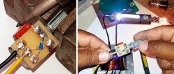
Let's assemble the circuit using wall-mounted installation. We form all the output parts one by one.

We solder the elements and use single-core wire as jumpers.

We connect the power cord to the diode bridge.

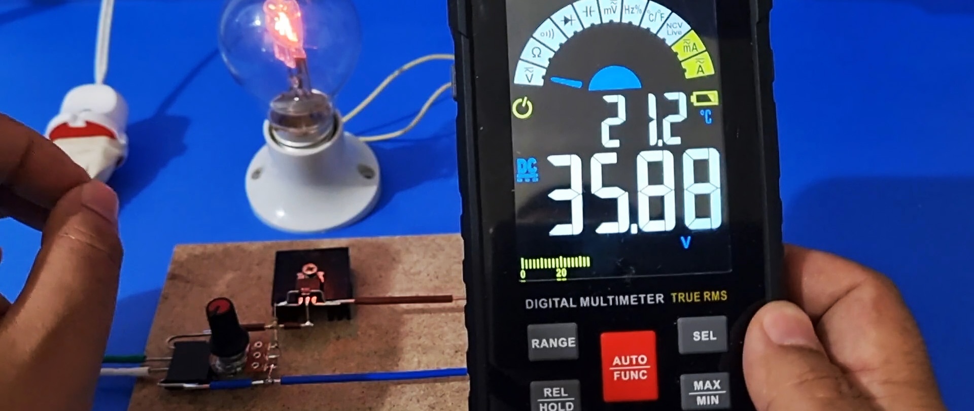
An incandescent lamp serves as a load. Connected in parallel to it multimeter.
We connect the circuit to a 220 V network.

By rotating the variable resistor slider we increase the voltage.

The adjustment is very smooth, without sudden jumps.


Advantages and disadvantages
So, let's draw a line and look at the advantages and disadvantages of this regulator circuit.
Pros: very smooth adjustment from zero to maximum, compared to triac regulators.
Minuses: low efficiency, low power (no more than 125 W), constant voltage regulation only.
Definitely such a scheme is capable of life, and will definitely find its application.